

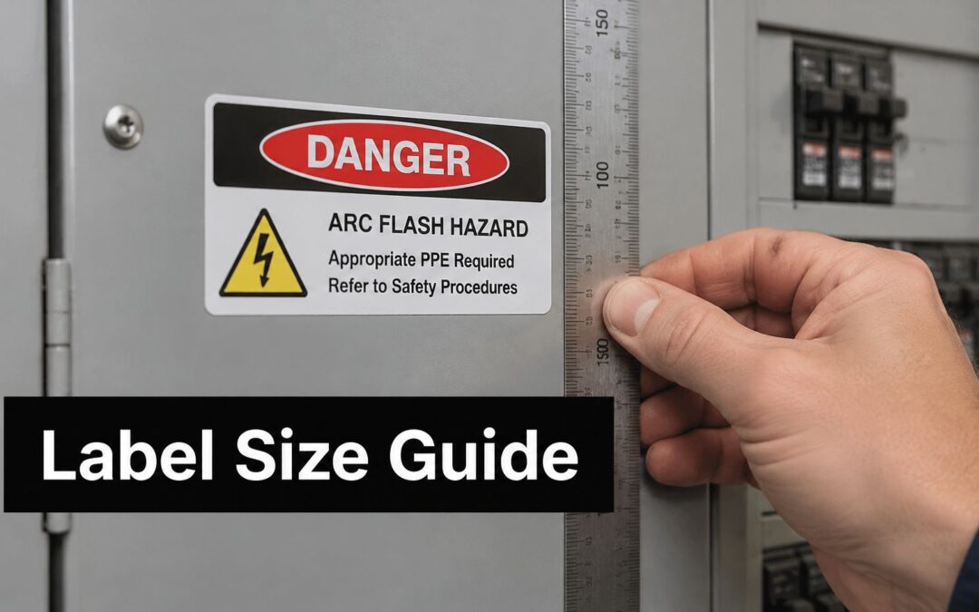
Choosing a standard catalogue size isn't enough to satisfy arc flash label size requirements in Australia. A label can fit neatly on a switchboard and still fail its purpose because workers can't read it before approaching the hazard, or because its information doesn't match the equipment's current operating condition.
The practical question isn't how large the label should be. It's what information must appear, where workers need to read it, and which specification governs the installation. Separate those decisions before approving artwork, and you're less likely to order a perfectly manufactured label that isn't suitable for the job.
Label Size Benchmarks Compared
The useful answer is a set of benchmarks, not a single universal size. The table distinguishes asset-owner requirements from supplier conventions so you can identify which dimensions belong in your procurement specification.
Arc flash label benchmarks and conventions
| Label or benchmark | Dimensions | Source | Use it for |
|---|---|---|---|
| Principal arc-flash warning | 237 x 182 mm | Water Corporation DS 29, positioned at about eye level | One per switchboard, where the client specification applies |
| Referral label | 100 x 100 mm | Water Corporation DS 29 | Certain incomer or supplementary warnings |
| Lower-risk warning | 170 x 120 mm | Water Corporation DS 29 | Defined lower-risk warning application |
| Catalogue size | 100 x 150 mm | Common supplier convention, no Australian legal basis | Only where it displays all required content legibly |
| Catalogue size | 125 x 175 mm | Common supplier convention, no Australian legal basis | Only where it displays all required content legibly |
| US product convention | 5 x 7 inches | US product convention, not an Australian minimum | Reference only |
| National minimum under AS/NZS 4836 | None set | Australian Energy Council guideline | Size from the risk assessment and viewing distance |
The asset-owner dimensions above come from Water Corporation's Design Standard DS 29, which specifies the principal, referral and defined lower-risk labels for its applications. The catalogue and overseas entries are product conventions, not evidence of an Australian legal minimum.
Read the authority behind the dimension
A client's engineering standard can prescribe a size even when the national standard doesn't prescribe a universal dimension. If your contract adopts DS 29, its applicable label requirements become part of the job's design and procurement requirements.
That doesn't make those dimensions mandatory for every Australian factory, hospital or electrical installation. Nor does buying a label with matching dimensions establish that its content, material or location is correct.
DS 29 also addresses information such as incident energy at the working distance, nominal voltage and minimum arc-rated PPE for relevant activities. Its principal label is therefore an engineered communication format, not a rectangle that another supplier can copy without checking the underlying assessment.
Procurement rule: A dimension without its governing specification is a purchasing preference, not proof of compliance.
Choose the specification before the template
A supplier's template can be a useful starting point when the project doesn't prescribe dimensions. It becomes unsuitable if the designer has to shrink critical values, remove task conditions or abbreviate equipment identification until workers can no longer interpret it reliably.
The referral label is another common source of confusion. A small supplementary warning shouldn't be substituted for the principal label just because it fits beside the incomer.
Before fixing a size, identify the asset owner's current standard, the approved risk assessment and the applicable Australian requirements. Ask the responsible electrical designer to resolve any conflict between them before the order reaches fabrication.
Why No Universal Minimum Size Applies in Australia
There isn't a standard Australian label dimension that you can apply to every board and then stop assessing the result. The absence of a universal size doesn't remove the obligation to communicate the hazard effectively.
Standards Australia's description of AS/NZS 4836:2023 identifies its scope as safe work on or near low-voltage and extra-low-voltage electrical installations and equipment, including arc blast, arc flash, electric shock and electrocution hazards. Its dedicated arc-flash labelling appendix makes it an Australian reference point, rather than leaving designers to rely solely on overseas product templates.
The Australian Energy Council's Electrical Arc Flash Hazard Management Guideline explains that a minimum label size cannot be recommended because labels need to remain clearly visible, well positioned and legible while presenting critical information concisely. It provides an information baseline rather than an arbitrary physical dimension.
Start with the information baseline
The guideline identifies the following information for the label:
- Bus or equipment name, so the worker can identify the equipment covered.
- Bus voltage, to identify the electrical system.
- Activity being performed, because the assessment must relate to the actual task.
- Incident-energy level, to communicate the assessed exposure.
- Arc-flash boundaries, to identify the relevant separation distance.
- PPE level for activities and conditions, including distinctions such as switchboard doors open or closed.
That last point matters when a board has different assessed conditions. A label that presents an energy value without explaining the applicable activity can encourage a worker to apply the wrong result.
Treat the label as a safety signal
The Energy Council recommends treating arc-flash labels as danger signage because the hazard may be life-threatening. The label's function is to influence a decision before exposure, not merely to identify equipment after a worker has opened it.
A coordinated switchboard labelling requirements guide is useful when reviewing how equipment identification, operational instructions and hazard warnings work together. Keep those functions visually distinct so workers don't have to search through unrelated asset information for a critical warning.
The resulting size follows from the required fields, readable text, available mounting space and intended viewing position. A larger panel doesn't automatically require a larger warning, and a smaller enclosure doesn't justify unreadable text.
Required Information Every Label Must Carry
Label content starts with the documented risk assessment and electrical study. A generic arc-flash symbol doesn't tell a worker which equipment was assessed, the exposure calculated for their task or the protection specified for that condition.
A.G. Coombs' guidance on safe working around electrical equipment identifies calculated switchboard fault level, phase-to-earth voltage, assessed working distance, open-panel incident energy, minimum PPE category and arc-flash-boundary distance among the assessment-based information. These are engineering outputs, not values for the engraver to select.
Use a field-by-field checklist
The checklist combines the Australian information baseline with fields used in infrastructure specifications and task-specific electrical safety arrangements. Not every supplementary field is a universal national requirement: the responsible designer must identify which fields the governing specification and assessment require.
Required arc flash label fields and their basis
| Information | Requirement basis | Why it matters on site |
|---|---|---|
| Equipment or bus name | Energy Council baseline and AS/NZS 4836 labelling information | Identifies which board the warning covers |
| Nominal bus voltage | Energy Council baseline and AS/NZS 4836 labelling information | Identifies the system voltage, but not incident energy by itself |
| Incident energy, in cal/cm² | Assessed value for the stated task and equipment condition | Supports selection of appropriate arc-rated protection |
| Working distance | Electrical study and infrastructure specifications | Gives the distance associated with the energy figure |
| Arc-flash boundary | Calculated thermal exposure boundary | Identifies where arc-rated protection is required under the work controls |
| Minimum PPE category | Risk assessment and applicable selection method | Communicates the minimum protection for the stated task |
| Limited and restricted approach boundaries | Applicable electrical safety assessment | Controls approach to electric-shock hazards, separately from the arc-flash boundary |
| Glove rating | Electrical assessment, where live work is permitted | Identifies the required electrical insulating protection |
| Assessment date and asset ID | Infrastructure specifications and document-control arrangements | Connects the physical label to the correct study and asset |
| Hazard symbol | AS 1319, as specified by the asset owner | Provides the specified safety-sign visual cue |
Read the fields in the order workers need them
Identification comes first. Equipment name, location or asset identification lets the worker match the label to the board and the permit, while the assessment date helps them locate the supporting record.
Electrical hazard values come next. Nominal voltage identifies the system; phase-to-earth voltage describes a different voltage relationship, and the calculated fault level records an important assessment input. Don't substitute one field for another because a template has only a single voltage box.
Energy values need their conditions. Open-panel incident energy must be associated with the assessed working distance and task, while the arc-flash boundary communicates a different distance altogether. Leaving out the working distance makes the energy value harder to interpret correctly.
Controls must be unambiguous. Minimum PPE, applicable approach boundaries and glove information should describe the approved work arrangement, not imply that live work is automatically permitted. A PPE category isn't permission to proceed.
The labelling provisions in AS/NZS 4836 require clear, legible danger-signage design, with equipment identification, voltage, incident energy, boundary and PPE information among the referenced content. The hazard symbol and header should support that information, not crowd it out.
A label missing an applicable study value cannot be fully checked against the study, whatever its size. Resolve missing fields with the responsible assessor rather than filling the space with a generic instruction to wear suitable PPE.
Viewing Distance, Mounting and Placement Rules
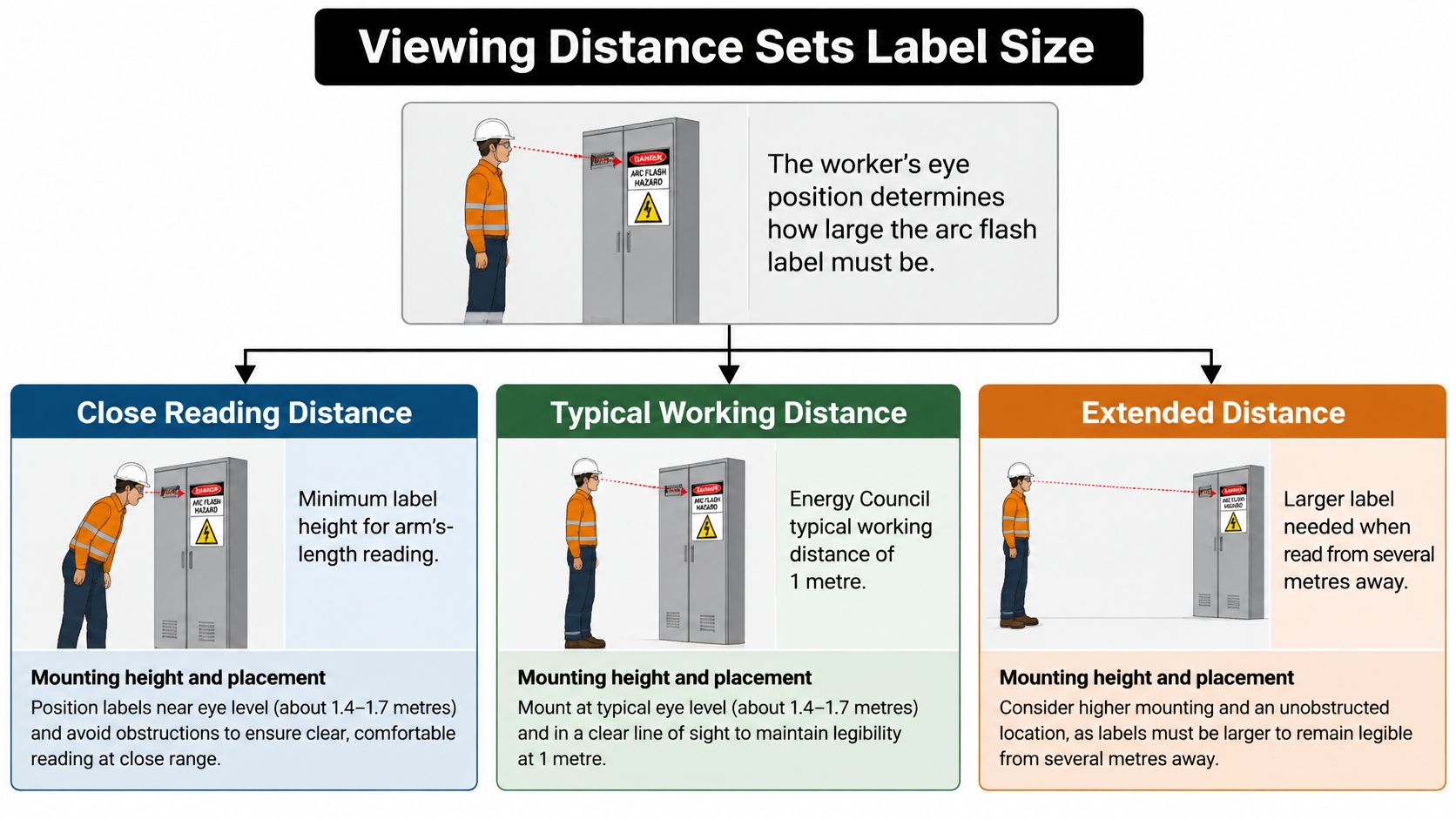
A worker needs to read the warning before stepping into the assessed work zone. Working distance is the distance tied to the exposure calculation. Reading distance is the spot where that person must recognise the message and decide how to proceed. Those two distances often differ. Neither one is a catalogue plate size, and a larger panel does not create a reading position that the study never assessed.
A road sign works on the same principle: lettering is sized for the point where the driver still has time to act, not for the moment the hazard already surrounds the vehicle. If the only readable spot on a switchboard sits inside the arc-flash boundary, the label is in the wrong place.
Use the diagram as a visual explanation of distance and layout, not as a substitute for the equipment-specific assessment.
Apply the mounting specification accurately
Asset owners and utilities publish their own mounting arrangements. Some place the bottom of the label near a standing eye line and require that position to sit outside the stated arc-flash boundary. Some use a warning header for lower hazard categories and a danger header for higher ones. Treat those choices as that organisation's specification. They are not a legal minimum label height or size, and they do not replace the equipment study.
Where the enclosure face would put the reader inside the boundary, have the designer resolve the location. Remote signage is one option when the enclosure itself cannot offer a safe reading position. Do not assume the enclosure face must take priority.
Utility practice often calls for more than one notice on a switchboard: a principal warning near the incomer, plus a further notice that directs a worker to the relevant part of the board. Battery systems are commonly covered by the same visibility rules, including rooms, cabinets and stands. A front-mounted warning should identify the incident energy and the PPE that apply to those parts, so one generic line is not left to stand in for the study.
Check visibility through the actual task
A principal label, a referral label and a supplementary warning can do different jobs, so more than one notice is not automatically a conflict. Check the proposed layout against the site's wider safety signage arrangements and inspect the enclosure in the operating states workers use.
- Door movement: Confirm that an open door will not hide the warning before access.
- Removable covers: Keep the principal warning where the board stays identifiable once covers are removed.
- Environmental damage: Look for heat, chemicals and abrasion that could obscure the message.
- PPE visibility: Check readability through the face protection required for the task.
Apply the same checks to battery cabinets. A front face is a poor warning location if workers normally approach from another side.
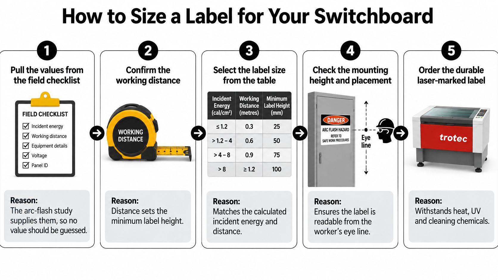
How to Size a Label for Your Switchboard
Build the layout from approved information, then test it at the intended reading position. Don't choose a blank first and force the assessment into whatever space remains.
Work from the study to the proof
Pull the approved values into the artwork. Use the equipment-specific study and field checklist, including task conditions and document references. Leave unresolved values flagged for engineering approval rather than guessing.
Confirm the arc-flash boundary. Eaton's explanation of arc-flash fundamentals defines it as the distance where incident energy reaches 1.2 cal/cm², with arc-rated PPE required inside that boundary. Use the calculated equipment result, not a standard distance copied from another board.
Establish the assessment and reading positions separately. Confirm the study's working distance for the equipment, then measure where workers will read the warning. If they must read before entering a controlled area, assess the layout from that position.
Lay out the complete text and symbols. Count the activity notes, condition headings and value rows, then measure the longest line in the actual font. A character count alone won't establish width because letterforms and typefaces differ.
Choose readable text before trimming the plate. Increase the label dimensions if the critical information becomes cramped, and check contrast on the proposed material. Inspect the proof under site lighting for reflections that hide text.
Check the governing size and available surface. Where the client prescribes a format, use that format and refer conflicts back to the designer. Keep clear of handles, ventilation openings, fasteners and enclosure features that prevent secure mounting.
Approve the location with the artwork. Confirm mounting height, visibility and the required relationship to the boundary. Record both the label drawing and its installation position so fabrication approval doesn't leave placement unresolved.
The process diagram summarises the design and production workflow. Material durability still needs verification for the selected substrate, marking method and environment.
A hypothetical artwork comparison
Suppose a low-voltage board needs an activity note running to four lines. For an illustrative proof, the designer chooses a 237 x 182 mm layout and measures its longest line at 190 mm, allowing the full activity description to remain together.
For another hypothetical board, the principal warning and PPE instruction are shorter, while the remaining required fields still fit below them. The designer trials 125 x 175 mm, with a longest line measuring 95 mm.
Those are illustrative artwork measurements, not prescribed sizes or text-width limits. The smaller layout would be unsuitable where the client requires a different principal format, and the larger layout would still fail if workers couldn't read it at the intended position.
Acceptance test: Every applicable value and task condition must be readable where the worker needs the information, not merely on a desktop proof.
Durable Materials and Laser Marking with Trotec Laser
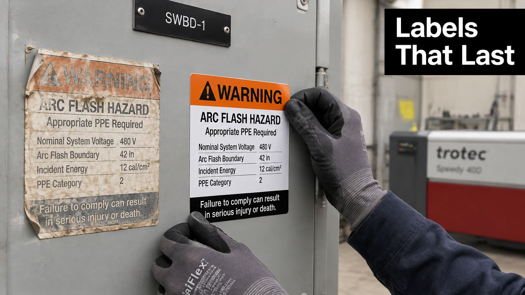
Sunlight, cleaning chemicals, heat and abrasion can wipe out a label that was readable on the day it went on. Specify the material and the marking system together. A durable plate does nothing useful if the contrast fades or the fixing fails.
The installation surface matters as much as the face material.
Match the finish to the exposure
Printed polymer labels can suit indoor boards with limited wear, provided the film, printing system and adhesive all suit the enclosure and the cleaning regime. Check that full construction. A phrase such as industrial grade does not do the check for you.
Engraved or laser-marked metal is a candidate where the cover is handled, cleaned often, or left in the weather. Select the alloy and the marking process for that environment, then judge whether the finish will still show enough contrast after the expected exposure.
A board in sunlight needs an outdoor material system that holds up under UV, not an indoor label printed on a larger sheet. Outdoor duty changes the material. It does not set a legal minimum size, and it does not make a catalogue size into a compliance size. Viewing distance, placement and the risk assessment still decide how large the label needs to be.
A plate on a removable cover is a separate problem. It can be tough and still be missing when someone needs the warning. Settle the permanent warning location before you choose adhesives or mechanical fixings.
Understand what the laser process does
Laser engraving and marking can be applied to suitable metal plates. Depending on the material and the process, the beam removes a little material or changes the surface, so the mark does not sit in a conventional printed ink layer.
That difference works like a house number cut into a plaque rather than a sticker stuck on the same plaque. The cut remains when the sticker peels. Engraving sets the information into the surface. Not every laser mark is a deep engraving. The process description alone does not prove resistance to heat, UV or a particular cleaner.
Use the electrical equipment label selection considerations to frame the material decision, then write the acceptance checks into procurement:
- Depth and contrast: Confirm the specified engraving or marking finish produces readable characters.
- Glare: Inspect a finished sample under the installed lighting and from different approach angles.
- Heat exposure: Check material and adhesive ratings against expected enclosure temperatures. Arrange representative testing without exposing workers to energised parts.
- Cleaning compatibility: Test the approved cleaning product on a sample and inspect both the mark and the attachment.
Specify the chosen material, finish and fixing method on the approved drawing. The fabricator then has a repeatable requirement, not an instruction to supply something durable.
Keeping Labels Accurate After Equipment Changes
A large, clear warning still misleads the next worker if the equipment behind it has changed. The mark can stay readable for years while the incident energy, supply source or operating mode no longer matches the text.
Treat the label as a controlled record of one approved assessment, not as proof that the assessment is still current. An accountable electrical person decides when that study needs review and when the label must be replaced. The printing or engraving supplier cannot judge whether a protection-setting change affects incident energy.
Make changes trigger a review
Build the trigger into maintenance and project change control before the work starts. A site drawing works the same way: the sheet can look official and still describe a circuit that no longer exists. Check the field against the record.
Review these changes before anyone relies on the existing warning:
- Switchboard alterations: Review changed compartments, conductors and equipment arrangements.
- Transformer or generator additions: Check changes to supply sources and operating configurations.
- Protection-setting changes: Assess the effect of revised settings and clearing behaviour.
- Network changes: Confirm whether the assessment's supply assumptions remain valid.
- Changed incident energy: Replace affected label information after the revised assessment is approved.
Temporary arrangements need the same discipline. A generator connected for maintenance, or an alternative operating mode, can make the normal permanent label wrong for the task in front of the worker.
A panel called decommissioned needs a verified status, not a reassuring description. Decommissioned and modified equipment has been involved in arc-flash incidents. Appearance does not prove that a board is isolated, that its study still applies, or that its warning is adequate. Equipment accessed under a permit should have its identity, isolation arrangements and applicable assessment reconciled before access is authorised.
Connect the label to controlled records
For a broader explanation of verification at handover, Axis Meter Solutions discusses why commissioning matters for building safety. Use commissioning and modification close-out to confirm that the installed equipment, documentation and warnings agree.
Link each label record to the single-line diagram, arc-flash study revision, permit arrangements and inspection schedule. Record who approved the content, where the label was installed and what change will trigger another review.
A durable label cannot compensate for an obsolete study or an unverified claim that equipment is decommissioned.
Include label replacement in project close-out rather than leaving it to the next general inspection. Withdraw superseded artwork so a later reorder does not reproduce an outdated warning.
Confirm the Label Size Before You Order
Approve the engineering basis, artwork and installation location before ordering the material. Procurement should receive a controlled label schedule, not a list of board names and a request for standard arc-flash stickers.
The final decision should demonstrate that the format satisfies the governing specification and remains readable in the actual work environment. A supplier can reproduce approved artwork accurately, but accurate reproduction doesn't resolve incorrect study data or a poor mounting position.
Complete the order checklist
- Name the governing specification. Record the asset-owner standard and applicable project requirements, including any prescribed principal or supplementary label format.
- Confirm the study revision. Have the responsible electrical person approve equipment identification, task conditions, values and assessment references.
- Record the reading position. Confirm measured viewing distance, mounting height and the worker's approach before approving text size.
- Specify the environment. Identify sunlight, cleaning products, expected temperatures, wear and the approved attachment method.
- Set the change-control trigger. Record who will review the label after electrical modifications or operating changes.
- Approve the physical proof. Check a finished sample, not just a screen preview, before releasing the full production schedule.
Keep artwork approval separate from engineering approval. The site supervisor can confirm visibility and location, while the authorised assessor confirms the hazard information and its conditions of use.
Test the sample where it will be read
At Evright Industrial, we offer engraving and marking projects and can advise on materials for asset labels and safety signage. Our sampling service allows customers to test different materials and marking finishes, and customers can be invited onsite to see the production facility.
Take the selected sample to the proposed installation position and assess it from the intended approach. Check the longest activity note, the smallest engineering value and any distinction between operating conditions through the relevant face protection, without entering an uncontrolled hazard area.
Each customer has a dedicated project manager as their key contact. That person works to the project's implementation schedule and budget and delivers any required samples for approval before production starts.
Before release: Approve the content, material, finish, dimensions and mounting position together.
If the sample fails, identify the actual cause before enlarging the plate. You might need less reflective material, clearer information grouping or a different mounting location rather than more surface area.
For the production method, evright.com's laser engraving capability uses a focused laser beam to mark the material's surface. With an engraved finish, the text is set into the surface rather than carried only by printed ink, although the selected material and process still need to suit the service environment.
Keep the approved sample reference with the artwork and label schedule. That gives future replacement orders a clear basis while preserving the requirement to recheck the study before reproducing old information.
Evright Industrial offers industrial engraving, asset labels and safety signage, with material advice and sampling to help confirm your arc-flash label layout before production. Visit Evright Industrial with your approved study values, governing specification and proposed mounting details to discuss a suitable material and marking finish.
Recent Comments