

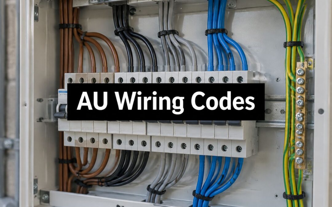
You're organising a switchboard upgrade, checking an equipment register or preparing a maintenance handover. The drawing says neutral, the cable is black, and a newer board nearby uses black for a phase conductor. Which identification should you trust?
The electrical colour code in Australia helps you recognise conductor functions, but it doesn't prove what a particular wire does. Cable type, installation history and later alterations all matter. Keep covers closed and leave conductor testing to a licensed electrical worker, especially when colours and labels disagree.
Current Electrical Colour Codes at a Glance
For the contemporary harmonised convention, the quick lookup is brown for single-phase active, blue for neutral and green/yellow for protective earth. The Weiss Electrical Wiring Rules guide describes conductor identification under AS/NZS 3000:2018 by intended function, including active, neutral, earthing and equipotential bonding.
Current fixed-wiring colours by function
| Function | Single-phase colour | Three-phase colour | Label text |
|---|---|---|---|
| Active | Brown | Brown, black and grey (phases) | L/A |
| Neutral | Blue | Blue | N |
| Protective earth | Green/yellow | Green/yellow | PE |
| Equipotential bonding | Green/yellow | Green/yellow | EPB |
Treat this as a harmonised-convention lookup, not an exhaustive list of every colour you may encounter in Australian fixed wiring. An electrician must establish which identification requirements apply to the particular installation, cable and equipment.
Read the function beside the colour
Brown, black and grey distinguish phases within the active-conductor group, rather than representing separate protective functions, so the label text must carry the meaning. Where individual phases need identification, the terminal and circuit documentation must distinguish them clearly.
Use L/A, N, PE and EPB alongside plain-language wording where space permits. Text remains useful when poor lighting, dirt, faded insulation or colour-vision differences make a colour difficult to distinguish.
Identification rule: Green, yellow and green/yellow must not identify an active or neutral installation conductor. Green/yellow identifies earthing and bonding functions.
For a safe self-check, choose a circuit shown on your closed switchboard's accessible schedule or drawing. Can you name its conductor functions without opening the board or relying solely on colour? If the site doesn't match this lookup, read Legacy Colours That Mislead on Mixed Sites before anyone touches the wiring.
What Each Conductor Does and Why It Matters
The label matters because each conductor has a different job. The element14 electrical wire identification guide distinguishes the active supply path, neutral return path and protective-earth fault path. Confusing those roles can expose people and equipment to electrical hazards.
Active and neutral form the operating circuit
The active, also called live or line, carries electrical energy from the supply to the load. A load might be a workbench power point, cabinet heater or machine motor.
The neutral provides the return path that completes the circuit. It isn't a spare earth, and its name doesn't mean it's safe to touch. A disconnected, incorrectly connected or faulty neutral can present a dangerous condition.
In a three-phase supply with a neutral, each active conductor carries a separate phase and the supplied circuits can share that neutral. Not every three-phase load needs a neutral, so don't infer its presence from the equipment's appearance. Protective earth remains separate from the normal load-current path.
Earth and bonding provide protection
Protective earth provides a low-resistance fault-current path so the appropriate protective device can disconnect the supply. Equipotential bonding connects relevant conductive parts to reduce dangerous differences in electrical potential between them.
Consider a metal equipment cabinet supplied from a bench power point. Its earth connection links exposed conductive metalwork to the protective system. If an active conductor faults onto the cabinet, an effective fault path allows the appropriate protective device to operate, rather than leaving the enclosure dangerously energised.
- Active mistaken for earth: An incorrect connection can energise exposed metalwork.
- Neutral mistaken for active: Misconnection can create unexpected voltage conditions or incorrect operation.
- Earth disconnected: Equipment may continue operating normally while an important protective measure is missing.
The codes in Current Electrical Colour Codes at a Glance describe these functions, not permission to connect matching colours. Legacy Colours That Mislead on Mixed Sites explains why an apparently familiar colour may represent another role.
Ask a functional question before accepting any identification: what would happen to this circuit if its earth were disconnected? If nobody can explain the protective arrangement, the circuit needs professional assessment rather than a better-looking colour label.
Flexible Cords Versus Fixed Wiring Colours
Conductor colours by cable type and era
| Cable type | Active | Neutral | Earth |
|---|---|---|---|
| Fixed wiring, current (AS/NZS 3000 harmonised convention) | Brown (single-phase) | Blue | Green/yellow |
| Fixed wiring, legacy | Red | Black | Solid green |
| Flexible appliance cords | Brown | Blue | Green/yellow |
The cable's purpose matters as much as its appearance. A flexible appliance lead and the fixed wiring supplying its outlet aren't necessarily identified using the same convention.
The Access Communications Australian mains plug guide lists brown and blue for flexible cords, but red and black for fixed building wiring, including its contemporary fixed-wiring description. That differs from the harmonised fixed-wiring convention used in the opening lookup.
Resolve the difference before making a connection
For new work, use the applicable standard's identification requirements as established by the licensed electrician, with the harmonised convention as the reference used here. Treat an encountered red conductor as potentially active until professionally verified, rather than deciding that it must be obsolete or incorrectly installed.
Say an electrician replaces an appliance plug and finds brown and blue flexible conductors. At the associated wall outlet, the fixed cable contains red and black conductors. The different colours don't, by themselves, establish a fault or tell the electrician which conductors can be joined.
A connection is determined by verified function and terminal identification, not by matching insulation colours.
A renovation introduces another trap: assuming that a familiar flexible-cord colour makes that cable suitable for fixed installation use. Cable suitability also involves construction, installation conditions, and the equipment connection, not just the colour of its cores.
Before assessing a termination, identify whether it belongs to building wiring, a flexible supply cord or equipment-internal wiring. Control circuits and imported machinery need their own applicable documentation rather than an automatic mains-colour interpretation.
Terminal markings, isolation and testing come first. A colour comparison is useful preparation for the electrician, but it isn't a connection instruction for a property owner or maintenance coordinator.
Legacy Colours That Mislead on Mixed Sites
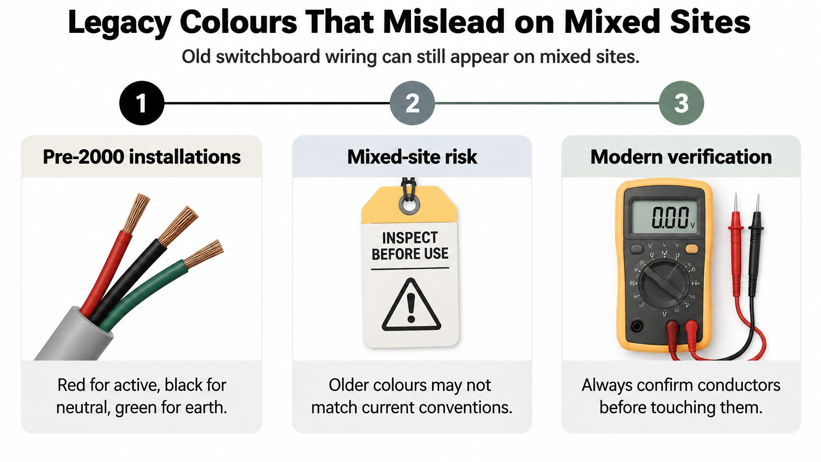
An older switchboard contains red, black and solid-green conductors, with circuit names but no clear function labels. A newer sub-board uses another scheme. The failed assumption is that every conductor across the site follows the same convention.
The RS Australian wiring colours guide places the substantial harmonisation change around 2000 and describes earlier common fixed-wiring colours as red active, black neutral, and green or green/yellow earth. During alterations, older wiring may remain beside newly installed cables, so the transition isn't necessarily visible as a clean boundary.
Old switchboard wiring can still appear on mixed sites.
Black and blue can reverse expectations
Black may identify neutral in older work but an active phase in harmonised three-phase wiring. Blue may identify a phase in older three-phase equipment but neutral in the modern harmonised scheme. Red commonly indicates active in legacy fixed wiring.
Those overlaps explain why an apparently obvious identification can fail. An electrician investigating a red conductor supplying a newer circuit must trace and test it, not assume that the age of the downstream equipment establishes the identity of the incoming cable.
Earth identification also needs care. Prysmian's conductor-colour safety guidance explains the restrictions on green, yellow and green/yellow for active and neutral conductors, while NSW Government electrical safety guidance notes that older installations may contain bare earth conductors. Neither solid-green insulation nor a bare conductor establishes an acceptable protective connection without considering condition and verification.
Replace assumptions with an action
- Older factory feeder with a newer sub-board: The failed assumption is that black means neutral throughout. Treat unidentified wiring as live, record its location and arrange licensed testing.
- Imported machinery: The failed assumption is that Australian building-wiring colours explain every internal conductor. Have the electrician identify the applicable equipment documentation and label the function established through testing.
- Repurposed control circuit: The failed assumption is that the conductor still performs its original role. Treat it as live until its present function and supply have been verified.
In a hypothetical older house, a retained red cable might feed newly installed equipment after a renovation. That is a mixed-generation connection requiring a verified circuit record, not a reason to infer function from whichever component looks newest.
Unknown means treat as live until a licensed electrical worker has tested it.
How to Date an Installation Before Trusting Its Colours
An installation date narrows the colour schemes an electrician might expect. It doesn't identify a conductor, establish the condition of its insulation or prove that later work followed the original arrangement.
Start with records, not the building's façade. A recently refurbished room can still contain retained wiring, while an older building may have a replacement switchboard and several generations of circuit alterations.
Build a traceable history
- Find the original certificate. Record the installation or compliance document's date and which work it covers.
- Read accessible board labels. Note handwritten circuit names, engraved plates and function markings, but don't treat their style as proof of age.
- Check alteration records. Identify additions, board replacements and equipment refits.
- Have visible sheath markings assessed. An electrician can interpret cable markings without assuming that a manufacturing detail dates the whole circuit.
- Compare renovation records. Establish which circuits each project changed and which it retained.
The transition history means a building's original installation date may describe only part of its electrical system. A date on a board replacement certificate doesn't necessarily date every cable connected to that board.
Record the evidence, not just the conclusion: Include where the date came from and whether the conductor identity remains unverified.
A useful hypothetical record reads: CCT 4, older fixed wiring, red assumed active, unverified, licensed test required. Add the certificate reference or renovation record beside it, so the next worker knows why that assumption was made.
Decision Guide When Colour and Label Disagree
A label is a claim about function. A colour is an identification clue. Neither overrides contradictory test results, and neither authorises work before the required isolation and verification are complete.
Action by colour, label and test result
| Situation | Action | Record |
|---|---|---|
| Colour matches label and test confirms function | Use the label for work within the verified isolation and work procedure | Record verified function |
| Colour differs from label | Stop; do not connect or switch | Escalate to licensed electrical worker |
| Legacy or imported colour with no label | Treat as live; licensed worker to isolate and test | Record function found by test |
| Solid green with no earth test result | Do not accept as earth until tested | Note age and condition |
A disagreement requires investigation
If a blue conductor carries an ACTIVE label, don't choose whichever interpretation seems more familiar. The label may be wrong, the conductor may have been repurposed, or the equipment may use a different identification scheme.
The electrician must resolve the discrepancy, determine whether correction is required, and update the record before release for work. Applying another label doesn't resolve a potentially non-compliant identification arrangement.
Any row requiring a licensed test remains a stop until the result is recorded. No row allows colour alone to decide the function.
How to Verify a Conductor Before Work Starts
Verification belongs within a controlled electrical work procedure, not an informal colour check. The Australian Government's ABLIS Wiring Rules entry identifies AS/NZS 3000 as covering installation design, construction and verification, and states that electricians undertaking installation or wiring work in the ACT must comply with it.
Only licensed electrical workers should test or alter installation wiring. The sequence below describes the checks a site should expect, not a substitute for electrical training, site procedures or the applicable requirements.
Establish safe access and identity
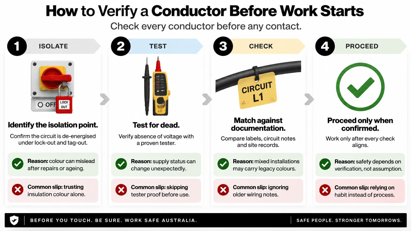
Identify and secure the isolation point. The electrician identifies all relevant supplies, isolates them and applies the required lock-out and tag-out controls. The common slip is switching off the wrong board or overlooking another supply.
Review labels, drawings and installation records. Compare the circuit designation, equipment identifier and expected conductor function. A familiar circuit name isn't enough if records describe equipment that has since been relocated.
Identify the cable and circuit type. Establish whether the conductors belong to fixed wiring, a flexible cord or equipment controls. Applying a building-wiring assumption to internal machinery wiring can produce an incorrect interpretation.
Prove the circuit dead before contact. Use suitable approved voltage-testing equipment and prove the tester according to the required procedure, including before and after testing. A dark indicator lamp or stopped motor doesn't establish absence of voltage.
The visual summary highlights the checkpoints, but doesn't replace the electrician's full procedure.
Verify the protective arrangement and record the result
Check protective-earth and bonding continuity, and verify polarity. The electrician uses appropriate installation test equipment and methods. Assuming that a connected green/yellow conductor has effective continuity is a common mistake.
Reconcile results with the identification. Record the verified function against the circuit and equipment, then arrange any necessary correction to labels and drawings. Don't leave the finding only in a technician's memory.
Stop at any conflict. Unexpected voltage, uncertain continuity or inconsistent identification requires investigation before work proceeds. Don't continue the sequence on the assumption that the discrepancy is merely cosmetic.
For project planning, our guide to Australian electrical safety standards provides context for coordinating identification with electrical safety obligations. The handover should preserve the test results, isolation details and corrected documentation for the next licensed worker.
Writing Labels That Show Function, Not Just Colour
ACTIVE L/A, CCT 4, SOURCE DB-2, ISOLATE AT MCB 12
A label in that format gives a maintenance worker more useful information than a brown tag alone. It states the function, identifies the circuit, names the source board and points to the isolation device, but only when each detail has been verified. On mixed-generation sites, colour is the hint and text is the instruction: black, blue and red can carry different meanings in older work, so a familiar jacket colour should never be asked to settle the argument by itself.
Choose wording and materials together
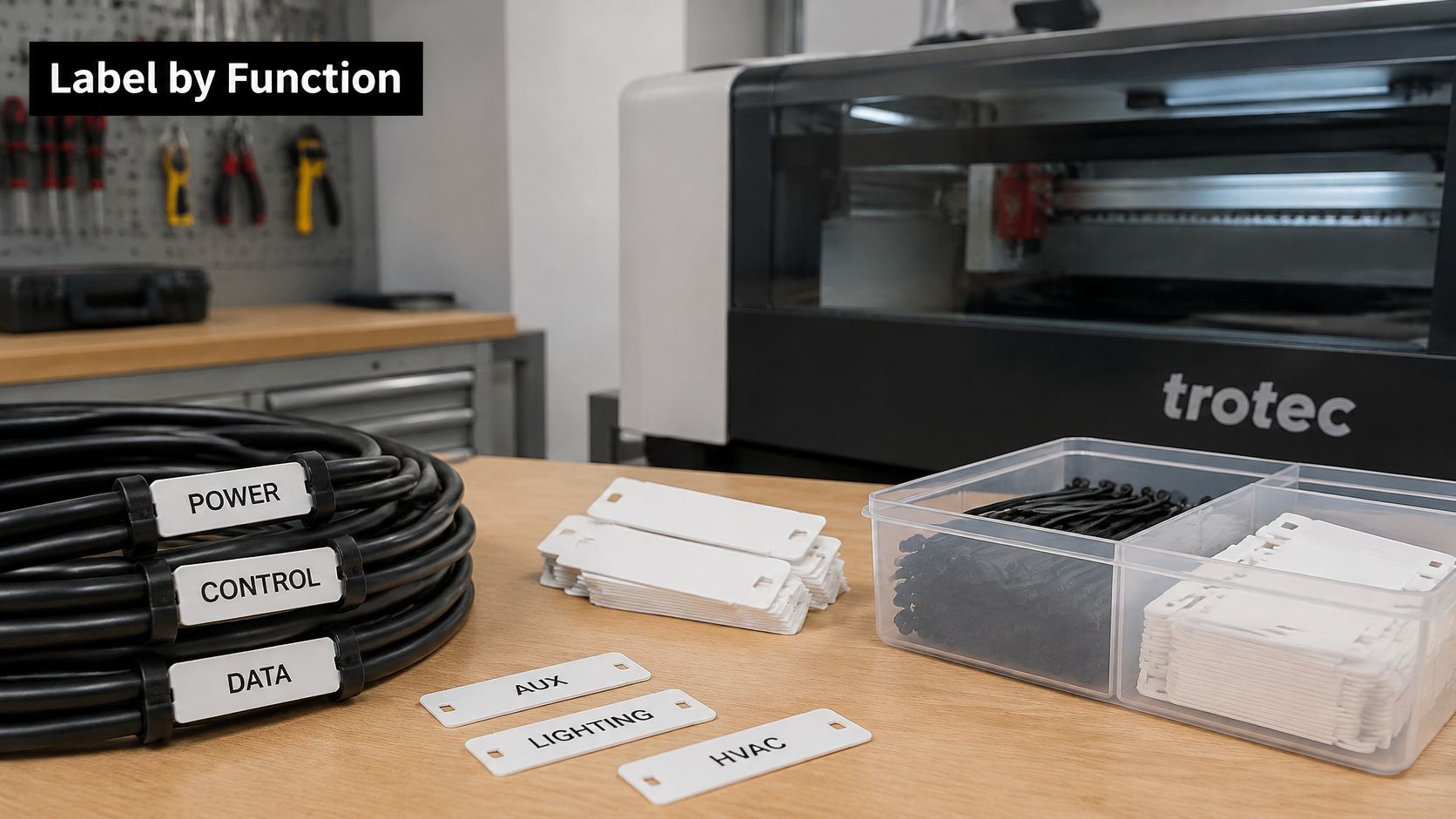
Use ACTIVE, NEUTRAL, PROTECTIVE EARTH, MAINS INCOMER and ISOLATOR where those descriptions apply. Pair them with L/A, N, PE or EPB when shorthand helps match terminal markings and drawings. The wording should assume the next worker arrives after the colour clue has already become ambiguous.
- Function: State what the conductor or device does.
- Circuit designation: Match the maintained circuit schedule.
- Source: Identify the supplying board or equipment.
- Isolation point: Name the verified device, not an approximate location.
If colour and text disagree, treat the conductor as unidentified until testing proves the role, then correct the label. A tag that says ACTIVE earns trust only when it records a verified result.
For heat, oil or abrasion exposure, consider a suitably specified metal plate with laser-engraved text rather than an ordinary adhesive label. Material, finish and mounting method still need to suit the actual environment. Laser marking removes or alters the surface to create legible identification; it doesn't depend on a separate printed sticker remaining attached.
Our electrical equipment label guide helps organise the information before marking. Evright Industrial produces asset labels, safety signage, steel plaques, panels and switch plates, and offers sampling so customers can test materials and marking finishes before finalising a specification.
Confirm Labels and Isolation Points Before Work Starts
A useful handover records what has been verified, what remains uncertain and who must resolve it. A neat circuit schedule isn't enough if its isolation references don't match the equipment on site.
Keep unresolved identification separate from released-for-work information. That prevents a colour-based assumption from being copied into the next drawing revision as though it were a test result.
Complete the handover record
- Verified function: Record the conductor role against the circuit and retain the supporting test documentation.
- Isolation reference: Confirm that the recorded isolation point and its accessible label agree.
- Function wording: Identify where text must supplement colour identification.
- Outstanding exceptions: Flag legacy wiring, imported equipment and unresolved discrepancies for licensed assessment.
Use our switchboard labelling requirements guide when preparing the identification schedule. Provide approved wording rather than asking an engraver to infer conductor functions from photographs.
For durable identification, contact us on 08 8231 2746 or sales@evright.com. We produce asset labels, safety signage and switchboard markings, and provide identifying markers for defence and essential services items.
The practical priority is an accurate handover, followed by durable marking of the verified information. Labels support verification; they never replace testing by a licensed electrical worker.
Turn your approved circuit schedule into durable, function-based identification for switchboards and electrical assets. Visit Evright Industrial to discuss laser-engraved labels and safety signage matched to your verified wording, mounting locations and operating environment.
Recent Comments