

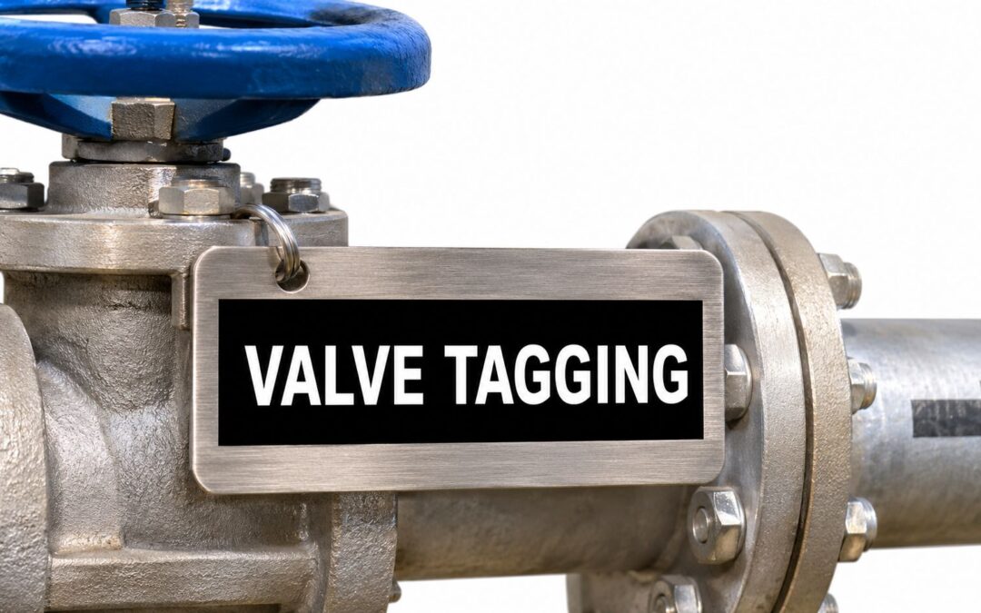
A valve tag doesn't make a valve safe. It tells your crew which valve they're looking at, and that's a different job entirely. Get that distinction right and the rest of your system, from valve tagging standards and colours to numbering and placement, falls into place. Get it wrong and you'll engrave temporary work details onto permanent markers, invent numbers that don't match your drawings, and order tags nobody can read after the first washdown.
Which Valve Tagging Standards Apply in Australia
No single document covers everything a valve tag must do in Australia. You'll need to work from several references, and each one answers a different question. The table below is where I'd start any specification review.
Australian standards that govern valve tags
| Standard | What it governs | What it means for valve tags |
|---|---|---|
| AS 1345 (pipes, conduits and ducts) | Identification by base colour, legend, symbols and flow chevron | Tag should match the connected pipe marker and sit beside the valve |
| AS 1319 (safety signs) | Colour and wording conventions for safety signage | Basis for colour and wording on danger and warning tags |
| AS 1357.2:2023 (control valves) | Control valves mainly used in heated-water systems | Specification reference for those valves, listed by the ABCB in 2023 |
| WorkSafe WA hazardous-energy isolation guidance | Danger, isolation and out-of-service tags, and locks | Tags communicate information only; a lock is required where practicable |
What Each Reference Actually Sets
AS 1345 is your identification standard. It treats the valve as part of the line, so colour, words, symbols and flow direction must read as one system at the point where an operator intervenes. AS 1319 doesn't tell you which valve you're on. It gives you the safety sign conventions behind danger and warning wording and colour.
AS 1357.2:2023 works at a different level again. In 2023, the Australian Building Codes Board list for valves listed AS 1357.2:2023 as the specification for control valves primarily used in heated-water systems. That's equipment specification, not a tagging layout, but it matters when you're confirming what type of valve the tag is identifying.
The WorkSafe WA isolation guidance is not an AS standard. Don't dismiss it for that reason. It governs the part most likely to hurt someone if it's mishandled, namely how temporary tags and locks are applied, who applies them, and what information travels with them.
Scope Worth Confirming on Your Site
AS 1345-1995 was reaffirmed in 2018, and the AS 1345-1995 standard listing records that it covers fluid services as well as electrical and communications distribution in land installations and on ships. That breadth is why a plant room, a utility corridor and a process area can all fall under the same identification logic even though the services differ.
First practical step: List which standards your P&IDs, isolation procedures and permit templates already cite. Your tag specification must match those documents, not a supplier's default template.
If the drawings cite a site standard that modifies AS 1345 colours, wording or numbering, that site standard controls the tag order. If they don't cite anything clearly, fix that before you manufacture tags. Ordering first and reconciling later usually means paying twice.
Why a Valve Tag Is Information, Not an Isolation Device
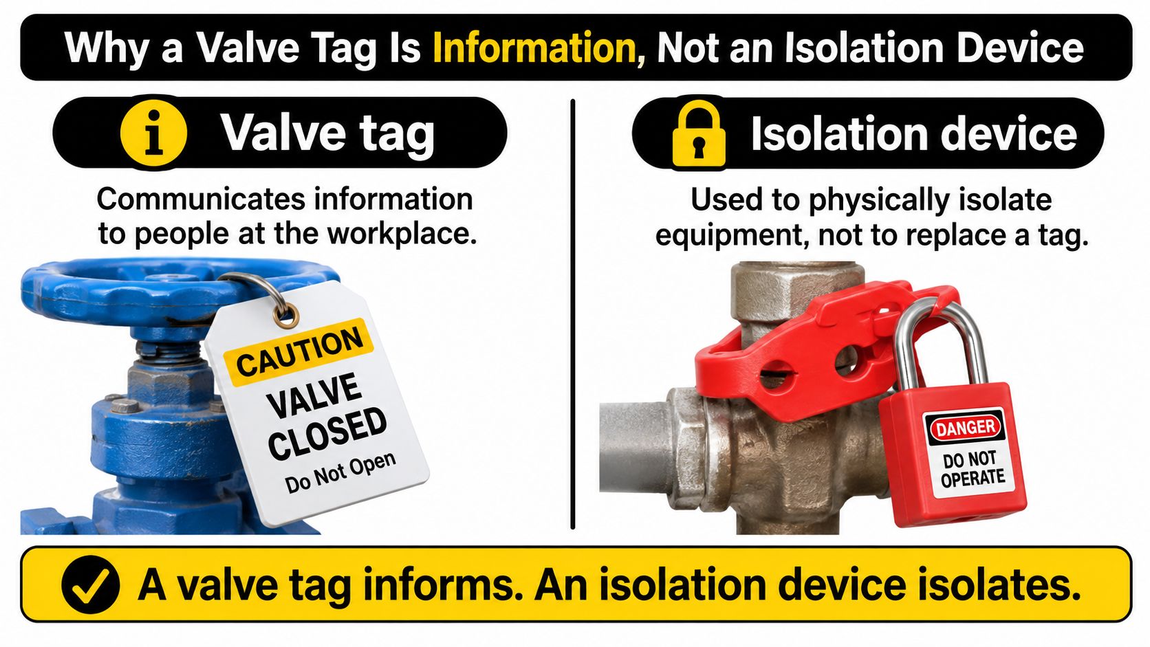
If you think hanging a tag on a valve has isolated it, you've misunderstood what the tag is for. Western Australia's WorkSafe guidance on isolation of hazardous energies states that a tag is not an isolation device and only communicates information to people at the workplace, and that where practicable, a lock must be used instead. The valve still has to be physically locked, isolated or otherwise rendered safe before work starts.
Think of a street sign and a traffic light. The sign tells you which street you're on. The light controls whether you can proceed. A permanent valve tag is the street sign. A lock is the control. Confusing the two doesn't make the plant safer, it only makes the paperwork look complete.
The Four Temporary Tag Categories
The same guidance identifies four commonly used tag categories, and they should never be collapsed into one generic tag:
- Personal danger tags: Accompany a lock and identify the person who applied it, the time and date, and the item of plant isolated.
- Isolation tags: Record the plant descriptor, unique plant identifier, any associated permit number, the reason for isolation, and the full name of the person conducting the isolation.
- Out-of-service tags: Communicate that plant is out of service. They don't protect a worker who's relying on that isolation for personal safety.
- Commissioning or testing tags: Communicate a temporary commissioning or testing state, which will change once that activity ends.
For isolation tags specifically, those five data fields are the point. They link a physical valve to a permit, a reason and a named person. If any one of them is missing, the next shift can't verify what was isolated or why.
The Two Layer System I Recommend
Separate permanent valve identity from temporary work status. That's the core of workable valve tagging standards on a real plant.
Say two identical gate valves sit side by side on parallel water lines. The permanent tag on each one should carry the valve number, service, flow direction and plant location. None of that changes when a fitter starts work on a Tuesday. The temporary tag for that job carries the worker's name, date, permit number and do not operate warning. When the job ends, the temporary tag comes off and the permanent identity is still correct.
Adding more text to a permanent marker does not improve safety. Mixing changing work status data with durable asset data makes the marker obsolete and ambiguous after the first shift change.
What the permanent marker must carry, and what it must never carry:
- Must carry: Unique valve or line identifier, service description, flow direction where applicable, and plant location or area reference used on the drawings.
- Must never carry: Worker's name, isolation date, permit number, reason for isolation, or a do not operate instruction tied to one job.
That separation also helps in emergencies. A responder who doesn't know today's permits can still identify the line, its contents and its direction from the permanent tag, then check the temporary tags and locks before touching anything.
Tag Numbering and Format That Match Your P&IDs
A valve tag should reproduce the identifier on the approved P&ID exactly. If the drawing, asset register and work documents use different formats, a technician may have to interpret the identifier in the field, increasing the risk of selecting the wrong valve.
Tag format examples and what each part shows
| Example tag | What it shows |
|---|---|
| Site P&ID tag | Designation and number copied exactly from the approved drawing |
| PSV plus equipment number | Pressure safety relief valve treated as an instrument |
| PCV plus equipment number | Pressure control valve treated as an instrument |
These examples are illustrative. Check them against your site's approved drawings before ordering tags.
Designations Are Not Optional Abbreviations
Water Corporation's Design Standard DS 81 for process engineering requires safety valves and control valves to be treated as instruments and tagged accordingly. It specifies PSV for a pressure safety relief valve and PCV for a pressure control valve. The designation identifies the device's function before the reader checks its number.
The standard's equipment tag numbering convention ordinarily uses five numerical digits, expanding to six digits for large, complex plants where process areas require more than nine P&ID sheets. The plant's size and drawing structure determine the format, not the tag size a supplier happens to stock.
Follow your site's approved convention and copy each designation and number exactly from the P&ID. Do not shorten PSV to SV, remove characters that appear redundant or renumber a valve to make a spreadsheet sequence neater.
Relief Valve Data Beside the Identifier
For relief valves, the identifier must lead to the correct supporting information. DS 81 requires relief valve set pressure to be shown in kilopascals gauge, kPa(g), with orifice sizing and relief case calculations documented. Your site standard determines whether the pressure appears on the physical tag or in a linked record. Either way, the tag must point unambiguously to the right set pressure and calculation.
A Simple Rule for New and Existing Plant
- Start from the drawing: Take the identifier from the current approved P&ID revision, not an old valve list or a photograph of a previous tag.
- Check the permit language: Confirm isolation certificates and permit templates use the same identifier. If they use a shortened form, correct the template rather than changing the tag.
- Set the format before manufacture: Record designation rules, digit count and separators in your site tagging specification so replacement tags remain consistent.
If you're building or cleaning up a register, set out your equipment tag number format before manufacture to avoid rework from ad hoc numbering. For a new plant, wait for the approved identifier before setting the tag format. This avoids clashing with the designer's convention or requiring drawing changes.
Matching identifiers let workers select the intended valve during lock, tag and try. A mismatch can direct them to a neighbouring valve that looks identical but may contain stored pressure or hazardous contents.
Colour Coding Under AS 1345 for Each Service
Choose the tag colour from the service shown on the P&ID, not from the valve's paint. AS 1345 uses base colours with contrasting lettering to identify pipe services. Use the following pairings as a guide, and confirm the exact shades against the current standard before ordering materials.
Pipe service colours under AS 1345
| Service | Base colour | Lettering |
|---|---|---|
| Water | Green | White |
| Steam | Silver-grey | Black |
| Oils and flammable or combustible liquids | Brown | White |
| Gases | Yellow-ochre | Black |
| Acids and alkalis | Violet | White |
| Air | Light blue | White |
| Fire services | Red | White |
| Electrical power | Orange | White |
| Communications | White | Black |
The Wattyl guide to pipeline identification colours lists water as green with white lettering and gases as yellow-ochre with black lettering. Apply the appropriate pairing to the tag as well as the connected pipe marker, so the service cue is consistent.
Applying the Colour to a Tag
- Confirm the service: Check the P&ID and line list. Valve-body paint alone is not a reliable service reference.
- Apply the pairing: Use the base colour as a band, border or background field, with the identifier in the contrasting lettering colour.
- Match the pipe marker: Keep the tag's service colours consistent with the connected pipe identification. AS 1345 identification can combine base colour, markers, words or symbols, and supplementary colours.
- Check local variations: Some water utilities set their own rules for label backgrounds, contrasting borders and flow chevrons. Confirm the applicable site or utility standard before finalising the artwork.
- Record unclear cases: If a valve controls mixed or unclear services, resolve the colour choice against the P&ID rather than selecting one during tag production.
A service colour is a cross-check, not a substitute for the valve's unique identifier. The identifier must remain readable and correct if heat, sunlight or chemicals fade the colour. Choose a colour treatment that can be read alongside the engraved number, and keep the number as the permanent reference.
Placement, Spacing and Legibility in the Field
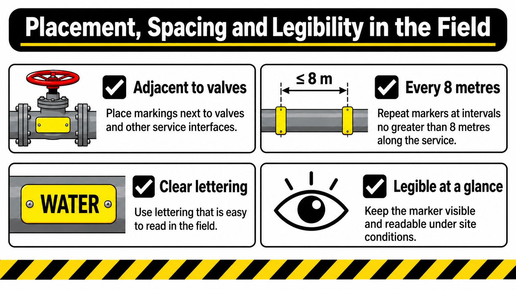
A valve tag only works if the person at the valve can read it and match it to the correct equipment. The University of Melbourne guidance on labelling pipes, conduits and ducts calls for markings adjacent to valves and other service interfaces, with intervals no greater than 8 metres along the service. It also specifies lettering large enough for normal eyesight, strong contrast and a chevron showing flow direction.
Where the Tag Has to Sit
Position the tag so it can be read from the normal operating approach, where a technician reaches the handwheel or actuator. Keep it clear of insulation, pipe supports, lagging bands and the handwheel. A tag that requires climbing or moving equipment to read is poorly placed.
Attach the permanent identifier to the valve body or bonnet area, without obstructing operation. If routine maintenance can separate the tag from the valve, choose a different attachment point. The identifier needs to stay with the valve through inspection and maintenance.
Where a special hazard exists for operators or maintenance staff, a yellow-and-black striped band is commonly used as a warning cue. Keep it distinct from the permanent valve identifier, which tells workers exactly which valve they are dealing with.
Close Valves and Separated Operating Points
Give each closely spaced valve its own identifier. A group reference at a manifold can supplement those identifiers, but it must make clear which valves it covers and how each is distinguished at the valve body.
If the accessible operating point and remote isolation point are in different locations, show the same identifier at both. Different local names can break the link between the permit and the equipment. During lock, tag and try, both workers need to confirm the same valve by the same number.
Walk the Line Checklist
- Readable from the approach: Can you read the full identifier without moving insulation, climbing or using a phone torch?
- Flow visible: Is the chevron present, correctly oriented and consistent with the adjacent pipe marker?
- Drawing match: Does every character match the current P&ID and asset register entry?
- Contrast intact: Does the lettering stand out in the area's poorest normal lighting?
- Unobscured: Is anything covering, abrading or swinging against the tag?
A tag that fails any check is not performing its identification function. Correct its placement, visibility or drawing match before treating it as present.
Engraving and Materials That Survive Plant Conditions
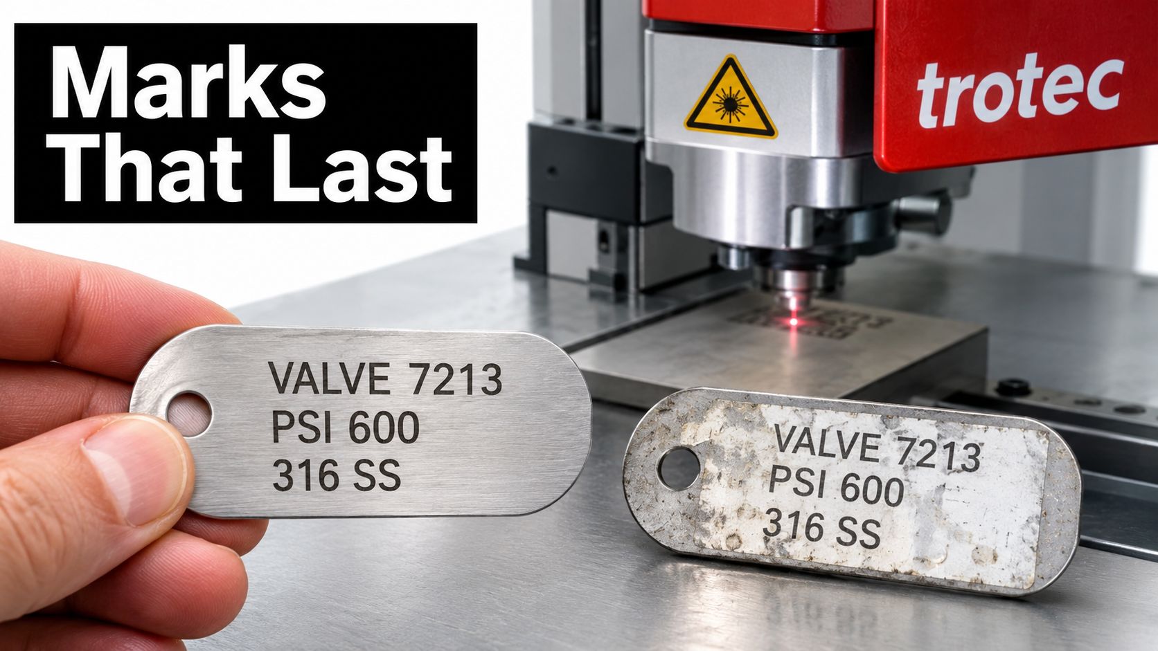
A valve tag must remain readable after washdown, chemical exposure, heat and routine maintenance. Printed labels can fail as adhesives lift, inks fade or corrosion spreads beneath a surface film. Engraving or etching puts the identifier into the tag material, rather than leaving it on a surface coating.
Laser marking produces a repeatable mark across a batch without ink, helping the identifier stay legible as the surface wears. Replacement tags should match the original in character shape, spacing and contrast so crews can read them consistently.
What to Specify in the Mark
- Engraving depth: Specify a mark deep enough to remain legible through surface wear, cleaning and light corrosion, without weakening a thin tag.
- Contrast: Use dark, anodised or filled characters where the environment allows. Check readability in the lighting where the valve is installed.
- Character discipline: Choose a clear typeface that distinguishes 1, I, 0 and O, and keep spacing consistent across the batch.
- Material fit: Select stainless steel, aluminium or another durable substrate to suit the chemicals, temperature, moisture and abrasion at the valve. One material need not suit every location.
Stainless steel equipment tags suit many corrosive and washdown locations. Check that the chosen material and mark remain legible under the conditions at the valve before specifying tags for the full plant. Evright Industrial carries out a full sampling and testing program before full production of customer-supplied items.
A Four Part Field Validation Test
Standards do not fully resolve how readable a tag will be around insulation, corrosion, chemicals, washdown, poor lighting, confined spaces or closely spaced valves. The Seqwater 2025 Safe Work with Plant Procedure shows plant-identification tags confirming the last inspection, test or calibration date. Use this four-part site check to assess whether a permanent identity tag will still work in the field:
- Readability: Read the tag from the normal operating approach, with insulation in place and under the poorest normal lighting.
- Confirmation: Match every character against the P&ID or asset register while standing at the valve.
- Resistance: Expose a sample tag to the site's corrosion, chemicals and washdown method, then check that it remains legible.
- Post-maintenance verification: Confirm the correct tag is refitted to the correct valve and remains readable before returning the valve to service.
A tag can be physically intact and still fail its purpose if its identifier cannot be matched to the correct valve. Replace it when the mark is unreadable or ambiguous.
Apply the test to a sample before full production. The result helps determine whether the selected material and mark suit the conditions at each valve, rather than assuming one specification will work everywhere.
Maintaining Valve Tags Across the Lifecycle
A permanent valve identifier must stay matched to the valve and its records throughout its service life. Valves get replaced, services change, and tags can be lost during shutdowns. Keep field tags, P&IDs and the asset register aligned by following your equipment tagging procedure.
Lifecycle Steps That Keep the Link Intact
- At commissioning: Record each tag against the approved P&ID and asset register before handover. Keep a photograph of the installed tag beside the pipe marker as an as-installed record.
- When anything changes: Update the tag and drawing together if a valve is renumbered or its line changes. The field identifier and record must agree.
- At inspection and test: Record inspection, test or calibration dates as required by the applicable site procedure. Keep inspection status current, and do not return equipment to service if required testing is overdue.
- For packaged equipment: Give each valve with its own P&ID identifier a separate tag, including a safety relief valve. A pressure gauge may follow the parent package where it has no separate identifier. Apply inspection tagging after each test, as required by site procedure.
- After maintenance: Check that each tag is back on the correct valve and remains readable before returning the equipment to service.
Own Identifier, Grouped, or Duplicated
Use the P&ID identifier to decide what the permanent tag identifies. A valve with its own P&ID identifier needs its own durable tag, whether or not it is operated independently. A valve without a separate identifier can be grouped with its parent equipment where the approved drawings and site register treat it as part of that package. Where the same identified valve has separated operating and isolation points, duplicate the identifier at both locations.
This keeps the register useful without obscuring an isolation point. A tag that is intact but cannot be matched confidently to the correct valve is not doing its job. Replace it or correct the identification before the valve is returned to service.
Confirm Your Tagging Standard Before Full Production
Confirm the standard before you order the batch, not after boxes of tags arrive. A short sampling run lets you test readability, colour contrast and drawing match at real valves, under real lighting, before full production locks in a mistake across hundreds of markers.
What to Bring to Your Tagging Supplier
- Drawing extract: The approved P&ID pages and the designation and numbering convention copied from them.
- Service colours: The AS 1345 base and lettering pairing for each line, plus any site or utility variation.
- Placement rules: Adjacent to valves, maximum spacing, flow chevron requirements and any special hazard banding.
- Temporary tag categories: Personal danger, isolation, out-of-service and commissioning or testing formats kept separate from permanent identity.
- Environment notes: Washdown, chemicals, heat, corrosion, insulation and lighting at the actual valve locations.
At Evright Industrial, we mark customer-supplied items, and customers request a quote for this from their project manager. Our range includes asset labels, safety signage, steel plaques, panels, switch plates, electrical switchboards, stencils, branding and laser cut architectural designs, so valve tags can be grouped with the rest of your site identification rather than ordered as a one off.
Here's how it works. Laser engraving marks the surface of the material, so the identifier stays readable as the plant wears, and you can see examples of that engraving work and the wider product range at evright.com. Send your tag specification, a drawing extract and details of a few sample valves to your project manager, approve the sampling results at the valves themselves, then release the full batch for a quote.
Stop guessing which valve controls which line and put a permanent, drawing-linked identifier on every independently operated valve. Talk to Evright Industrial about laser engraved valve tags, asset labels and safety signage made to your P&IDs, service colours and site conditions. Send your specification and drawing extract and we'll help you sample, test and produce tags your crew can still read after washdown, maintenance and years in service.
Recent Comments